
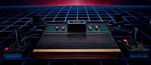
How does an Atari VCS work?
This is still going to be a huge page - but that's okay. There are aa bunch of big images here - but I've squeezed them down to 25k a piece, so it should go pretty quick even for 28k users...
Like a computer, the Atari 2600 VCS:
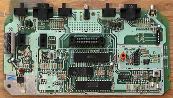
Here's what the different parts of the Atari look like and do (I'm using a Jr. board, because it's the best laid out board, and is very similar to all other incarnations in size and basic layout):

The highlighted item is the cartridge connector. The cartridge connector is a 24 pin female card edge connector (12 pins on a side) that is connected to power, ground, and the address and data buses of the big 3 chips.

The controller ports and related coponents are highlighted here. The controller ports are 9 pin D-sub connectors, and the resistors and capacitors associtade with them help with the correct amount of power, as well as protecting the lines from noise and feedback. From here the signal lines travel to both the RIOT and Stella chips.

This is the power circuit. It normally takes 9 Volts DC from the power supply, then knocks it down to 5 volts that the console uses. Technically, the power circuit can take anywhere from 6 to 35 volts (the voltage regulator can handle that much) but it's not recommended.

The color reference circuit takes both 5 and 9 volts and, using a potentiometer (variable resistor) sends a baseline voltage level to pin 10 on the Stella. The Stella uses this voltage as a reference for the luma signals, which then affects the color of the resulting image. The potentiometer (pot) allows the factory or service personel to tweak the color output to an "ideal" balance.

The heart of the Atari and former bane of my project, the clock circuit. Like modern computers, all three chips require a clock signal to drive them. What's used in the Atari is a 3.579545 MHz crystal, which matches the frequency of the NTSC signal. The tricky bit is that the crystal generates the oscillation, but the electrical signals are not discrete - the rest of the circuit helps make the clock pulse more distinct. This clock circuit is in most VCRs, DVD players, and TVs (and just about anyhting else that interfaces with a TV), which enabled me to find an alternate circuit schematic that I had better success with.
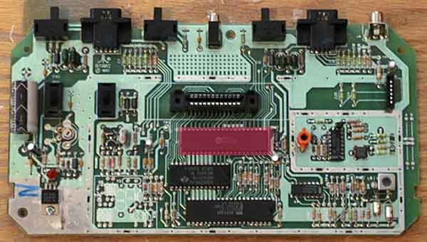
The RIOT chip - a 6532 IO processor with 128 Bytes of RAM! A very small amount indeed, but clever programmers can use it for a vast array of information. The RIOT is primarily responsible for reading the cartridge, controller, and switch information - though the Stella handles the paddles and fire buttons. The RIOT is housed in a 40 pin Dual Inline Package (DIP).
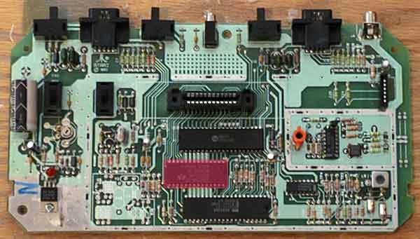
The 6507 CPU. A slimmed down, less expensive (at the time) version of the ubiquitous 6502 processor, which has been used in the Commodore 64, Apple II series, and Furbys. Yep, the 6502 is extremely flexible -aren't you glad it's the brain of the Atari VCS? The CPU is a 28 pin DIP packaged chip.

Ah, the Stella Tellevision Interface Chip (TIA) - named after an employee's bicycle - not a female employee - the Stella chip is responsible for creating the sights and sounds of your fvorite (and not-so-favorit) Atari games. As mentioned before, the paddle and fire buttons are also attached to the Stella. The Stella is a 40 pin DIP packaged chip.

This is the entire Audio/Video (A/V) subsystem. Signals from the Stella are manipulated and combined, then sent to the RF modulator so that they can be "tuned in" on channel 3 or 4 of any TV.

Finally, the RF modulator. Responsible for making the A/V signal look like a "tunable" channel to any TV.
Before we go further, it's important to know how a TV works, so if you need to, please visit the page below on TVs, then come back...
Okay, there is one very important thing to remember about how the Atari 2600 draws to the screen, which is different from just about any other console, or even modern computers - The Stella chip doesn't have any video RAM.
What does that mean? It means that the programmer is responsible for drawing to the Stella at the same time that it's drawing to the screen! This complicates things, but also allows for some interesting trickery.
Here's a snip from the Stella Programming Manual, by Steve Wright, 12-03-1979, which does a great job of explaining how this works:
Here's a picture to help explain things. The blue area is the actual atari screen, the black square is the actual size of a TV screen, and the gray area represents the time the program has to do its real work:

So, knowing this, we can explain why many games have those little black lines on the left side of the screen: the programmers needed a few extra clock cycles to change colors of the player or background - which is why those little black lines normally show up on color transitions! Maybe they won't be quite so annoying now that you know they make 2600 games more colorful!
So, that about wraps it up! If you have any questions, please let me know, I'd love to add to these pages and answer them!
Look at another section of how an Atari 2600 works:
- Atari 2600 console - processes controller input and cartridge instructions to create video and audio which are output to the TV
- Atari power cable - takes household current (120 Volts, 50-60Hz AC in the US) and transforms it into 9 Volt DC, roughly equivalent to a 9 Volt battery.
- Controllers (joysticks, paddles, keyboard controllers, etc...) - Transform human movement into signals the console can understand.
- RF cable and switch box - Sends the signal from the console to the TV's tuner as if it were a broadcast channel
- Television - The only way to see and hear what the console is producing
- Cartridges - Contain programs that are "run" by the console, which in turn, determine the sights and sounds generated by the Atari.
Comments? Questions? Answers? Email me!