
How do I get Composite Video and Audio out of my 2600?
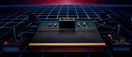
We all know that externally, the Atari 2600 generates a tunable RF signal that you connect to your TV via a cable and that fun little switchbox. (if not, read the How An Atari 2600 Works detail pages)
Internally, however, the Atari generates seperate signals for the video and audio, and we can tap into that!
Why would we want to do that?
- Clear picture
- Clear sound
- No more RF switchbox
- Easy to connect to almost any TV, VCR, Video capture card, etc...
There are a few requirements - you need to be comfortable with a soldering iron, a drill, and basic electronics.
Disclaimer:
Since we will be opening your VCS and attacking it with a very hot soldering iron, it is possible that you will render your system dead. Neither I, Classicgaming, nor Gamespy are responsible for any damage done to yourself, your Atari, your family, your pets, your house, your neighborhod, or your precious Faberge egg collection that results either directly or indirectly from you even reading these instructions, let alone attempting the modification described.
Okay, we have that out of the way - here's what you'll need, most of which can be purchased at you local Radio Shack, or favorite electronic parts store.
Okay, Let's do it!
Open your Atari
Whether it's a 6 switch, 4 switch, or Junior, they all come apart by removing screws from the bottom of the case and lifting the top off.
Remove the screws holding the PCB (Printed Circuit Board) to the bottom of the case, and carefully remove it from the case.
The aluminum cage around the majority of the board is there to shiled the rst of the world from the RF interference created by the system.
Remove the shield carefully by rotating the tabs to fit through the slots and pull apart.
You'll want to hang on to them and reinstall them when you are finished.
You do not need to remove the shield from the RF modulator.
Connect a bunch of wires to things
The entire purpose of this circuit is to mix the video signals in the right ratios so that we have a clear composite video signal.
Take six lengths of wire (give yourself plenty of wire, you can always cut them down), and solder them to the following pins on the Stella Chip: 2,5,7,8,9, and 12.
You don't know which chip is the Stella?
For all 2600 units, the Stella chip is basically in the same spot. Look for the big 3 chips, two of them are 40 pin DIPs and the center one is a 28 pin DIP (Dual Inline Pin).
The Smaller, center chip is the 6502 CPU, the chip closest to the cartridge connector is the RIOT (most of the cartridge pins are connected to the RIOT, so it makes senese for them to be close). and the big chip farthest from the cartridge connector is the Stella.
You don't know which pin is 2?
For All DIP packaged chips, there is a notch or dot on one of the non-pin edges.
Rotate the board so that the notch or dot on the Stella faces to the left.
The bottom row of the pins goes from 1 to 20, left to right, and the top row goes from 21 to 40, from right to left, like this:
Now flip the board over, and locate the pins for the Stella - the pin numbers are now mirrored:
Also notice that when you are looking at the underside of the board, one of the pins will be soldered to a square pad - that is always pin 1, and the other pins count away from it.
Now let's solder a decent length wire to ground, which is normally the large blocks of exposed metal covering different areas of the board.
If in doubt, use the exposed metal that the RF shields were attached to, or solder directly to those areas (make sure that you can still put the shields back on)
While we have everything out, we'll add wires to the RCA jacks too.
Solder a 9" length of wire to the center pole and outer shell of both jacks.
Mark one with an "A" and one with a "V"
Build the circuit
Now we'll build the video mixer circuit, here's the schematic:
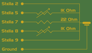
Place the three components on your board, spaced well apart.
The potentiometers (pots) have 3 pins, we only need two; there are two pins along the "flat" side - they do the same thing, we only need to connect one of them, and the single pin centered on the "curved" side.
Connect the wires from Stella 5 and 8 to the flat side of a pot, one wire per pot (it's best to put the wire throuhg a hole next to the pot and solder them together underneath).
Connect the wire from Stella 7 to one end of the resistor and solder them together.
Solder three smaller lengths of wire to the opposite ends of the pots and resistor.
Tightly twist together the three smaller wires and the wires from Stella 2 and 9, as well as the wire from the center of the "V" RCA jack and solder together.
Tightly twist the wire from Stella 12 to the wire from the center of the "A" RCA jack and solder them.
Tightly twist the wires from the outside of both jacks and the wire from the ground of the Atari board together and solder them.
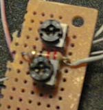
A closeup of the mixer board:
Test it out
Before we put anything away, we want to make sure that it works, so plug the system in, and insert a cartridge.
Connect an RCA cable from the "A" and "V" jacks to the Audio and Video input of your TV or VCR (tuned properly to receive the signal - many TVs or VCRs call this AUX, INPUT1, or INPUT2).
Turn the Atari on, and you should see a sharp picture, and hear clear audio when you start the game.
If the colors are off, adjust the pots, one at a time, with the small screwdriver until you are satisfied - you may want to try multiple games to make sure you have it adjusted correctly.
If you have do not have audio, video, or the video is missing a color, check the connections that you made, normally a wire is loose coming from the Stella.
Clean up
Now that everything's working, turn all power off, and trim the excess wire from your joints.
Completely cover all joints with electrical tape, including the backs of the jacks and the underside of the mixer board.
Cut or drill holes for the new jacks, and screw the jack plate to the case.
Replace the shields, and re-mount the Atari board to the case.
Close the case, and screw it back together.
Enjoy
Plug all of the cables back in, and have fun!
Comments? Questions? Answers? Email me!